T01 - Led Blink
Led blink is a simple use case to create an AAS Digital Twin (DT) of a Led, then to monitor its state. In detail, a led integrated with a Raspberry Pi (RPi) has two states ON and OFF. When a user click on a button on the RPi, the led switch its current state (from ON to OFF or from OFF to ON). The information can be monitored from the distance due to using an AAS DT of the led.
Requirements
The following components are required:
Network 192.168.56.0/24
Raspberry Pi 2/3/4/5 with pre-installed Docker
Led, button, and breadboard.
Computer with pre-installed Papyrus4Manufacturing
LocalSEA T01 Kit including some ready-to-run software components
The following knowledge are required:
Basic about Networking
Basic about Java + Eclipse IDE
Basic about Docker
Deployment Instructions
In this example, the computer has the IP address 192.168.56.11 and the RPi has the IP address 192.168.56.18. After downloading the T01 Kit, decompress it to get the two packages: (1) led_arm_v0.1.tar.gz contains the Docker image for the RPi, and (2) T01-LedBlink.tar.gz contains the AAS model design for the computer.
Led setup
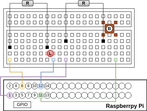
Figure 1 illustrates the schematic view of connecting RPi, led, button, and breadboard. In this fiture, L means led, B means button, R means register.
On the RPi, install and run the Docker image with the following commands:
$ docker load -i led_arm_v0.1.tar.gz
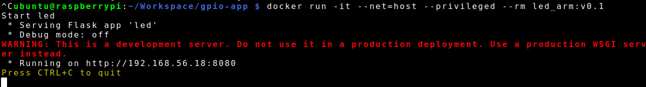
$ docker run -it --net=host --privileged --rm led_arm:v0.1
The expected result is shown in Figure 2. A server runs a simple program
to control the led, and it is exposed at
the endpoint http://192.168.56.18:8080.
To test if the led work, users can click the button, and verify the led’s state using the following command.
$ curl http://192.168.56.18:8080/state
When the led is on, the result of the above command is True. When the led is off, the result of the above command is False.
Led AAS DT setup
On the computer, extract T01-LedBlink.tar.gz with the following command:
$ tar -xzvf T01-LedBlink.tar.gz
Open Papyrus4Manufacturing and import the project as in Figure 3. The AAS Design Diagram shows the basic elements of the project. Note that users can see property state inside submodel Basic.
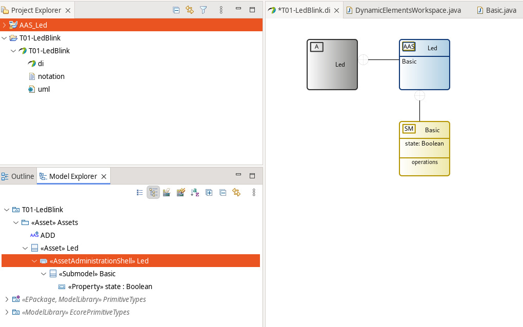
In Model Explorer, right click on the AssetAministrationShell Led,
choose AAS, then click
Generate Asset Administration Shell Basyx code (AAS).
When a new project AAS_Led is generated, users open the file
DynamicElementsWorkspace.java inside the package basic and modify
function get_Basic_state( ) as follows.
public Boolean get_Basic_state() {
  // Work with your Dynamic Property here.
  Boolean defaultVar = Boolean.valueOf(connectedDevices.ep_http.readValue("/state"));
  return defaultVar;
}
To run the AAS server including the Led AAS DT in Project Explorer, right click on AASServer.launch, choose Run As, then click AASServer. To test if the server work propertly, users can run the following command to get the AAS information model brief structure as output.
$ curl http://127.0.0.1:1067/aas
Verification
If all the above setups are correct, then the led AAS DT is connecting to the physical led. The aim is to get the state of the led through the AAS API. The following command is to get the state every one second.
$ while true;
$ do curl http://127.0.0.1:1067/aas/submodels/Basic/submodel/submodelElements/state/value;
$ echo '';
$ sleep 1;
$ done
Users click the button and check if the output showing on the prompt (True or False) corresponds to the led’state (ON or OFF).